Piping Engineering World
2.6K subscribers
About Piping Engineering World
Hello Guys In these Channel. Daily you can get updates, PDF Books, Presentations,Notes and more Files about Piping Engineering
Similar Channels

Hello 👋 Family

𝕱𝖗𝖆𝖘𝖊𝖘 ❤🔥 𝕯❜ 𝕭𝖆𝖓𝖉𝖎𝖉ó𝖘🥷

Daily Update Kare | Daily News | Fact

Books

Chacra TV

Ani Jae

Daily News Update

Arena Study - GovtJobs Update, Sarkari Yojana & Study Material With PDF Notes

Tech Guy

Daily Updates

Clash of Champions

Pooja’s Tanjore paintings

Daily Update 🔥🔥

𐙚⋆˚gigie’s daily update °˖ ✿

تصميم مواقع | UI/UX
Swipe to see more
Posts
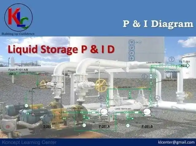
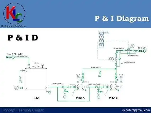
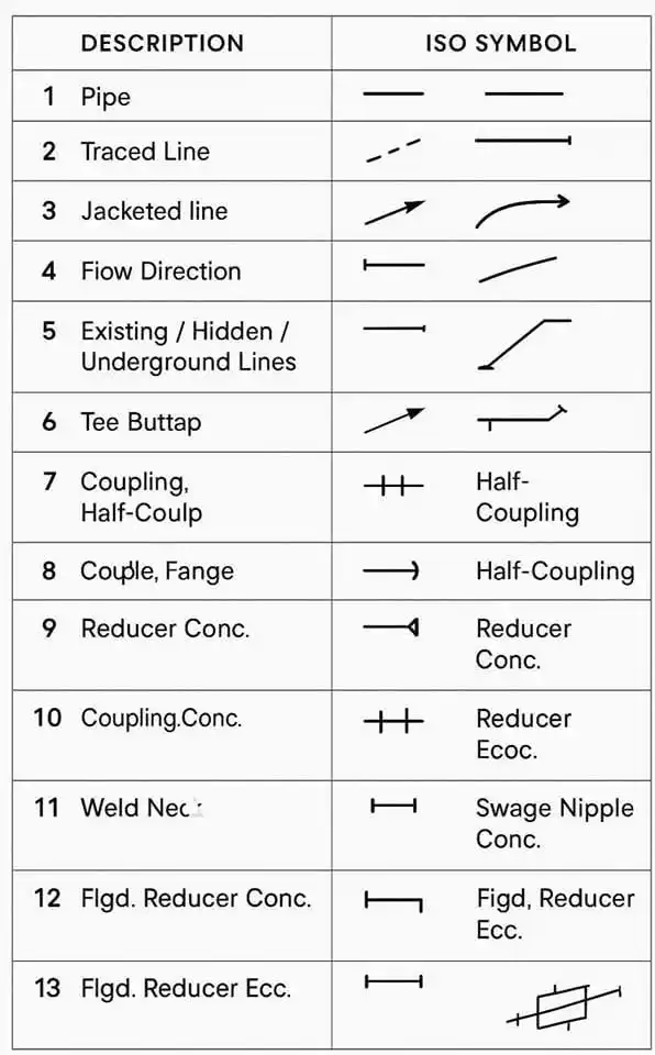
#Isometric drawings of pipes Isometric piping diagrams are isometric representation of a single pipeline in the factory. It's the most important output of pipeline engineering department. Pipe manufacturing work depends on isometric drawings. The isometric diagram of pipes consists of three sections. The main section consists of isometric representation of the pipeline path in 3D space, and includes the following information: 1. The line number. 2. The direction of the flow 3. Poster signs and props. 4. Site of pipe components. 5. Welding sites. The section to the left or right of the drawing includes a material list section for the portion of the line that appears in the isometric drawing. This section includes the following information for all components: 1. Describing the ingredients. 2. The ingredient code. 3. Nominal size. 4. Quantity. 5. Whether material for manufacturing shop or field work. 6. The number of pieces. The title bar section at the bottom includes the following information: 1. Project details such as client name, engineering office name, project name, project number, project processor license, etc. 2. Pipeline details such as line number, line size, isolation, tracing, liquid code, operating and design pressure and temperature, pressure testing method such as hydraulic or aeronautical test, test pressure, pipe material category, inch diameter, etc. Accounts: Inch Meter = Length of pipes in meter x Size of pipes in inch Inch Dia = size of pipes in inch x number of connections Isometric Diagram Checklist: The isometric diagram should be checked according to the project's isometric diagram checklist. This list includes general points as well as project-specific points. Symbols of Isometric Graphics Description: Link of codes Project-specific instructions for testing isometers: Each project has its own requirements. These requirements should be reflected in isometric diagrams. Some of these requirements may relate to: 1. Pressure Safety Valves Screw Supply Range (Input/Output) Bolts and bolts in the line, inlet or exit. 2. Fire fighting lines Pipe cutting requirements. Types of edges (flat edge or high edge). 3. Ventilation and practical drainage Ventilation and drainage requirements for hydraulic testing. Direct distance requirements for flow meters. 4. Insulation of pipes Isolation fish and its range. 5. Selection of valves / alignment 6. Requirements of jack score rim. 7. Identification of the Pros. 8. The requirements of connections / lovers. 9. Dimensions of galvanized pipe cutting. 10. Signs of the rooster crowing. 11. Notes of mounting props. 12. Channeling the rim of the Orivice. 13. Sequence of delivery in PID layout 14. Edges/fills and bolts at the end of iso sheet. 15. Philosophy of disconnection of paper. --- The professional post: 🔧 Everything you need to know about pipe isometric drawings! 🛠️ Isometric drawings are an essential component in the design and execution of piping in industrial projects. In these graphs, you can find everything about the pipeline, from line number to welding locations and props. These drawings are the document on which the piping department relies on to carry out the work accurately and professionally. 💡 What the isometric diagrams include: 1. Basic information such as line number, flow direction, and pipe supports. 2. Detailed information such as details of materials, sizes and quantities. 3. Tests and methods of testing pressure like hydraulic or aeronautical. 4. Special project requirements such as safety valves, isolation requirements and isometric graph codes. 📊 Special project modifications include: Safety valves Fire fighting lines The requirements of isolation Steering the edges Requirements of Rolled Edges
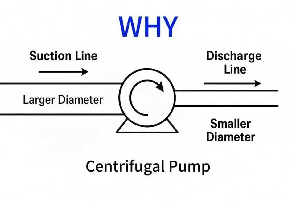
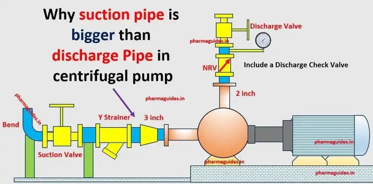
In a centrifugal pump, Why is the suction line diameter usually larger than the discharge line diameter? 1. To Reduce Friction Losses in Suction a. A larger suction pipe means slower fluid velocity. Lower velocity = less friction loss in the pipe. b. This helps maintain higher pressure at the pump suction. Less friction = higher NPSHa (Net Positive Suction Head Available), which helps prevent cavitation. 2. To Maintain NPSHa Above NPSHr a. Cavitation occurs if pressure at the suction drops below vapor pressure. b. A large diameter reduces pressure drop, helping to keep suction pressure above vapor pressure. c. This is especially critical in high-flow or hot fluid systems. 3. Discharge Side Can Handle Higher Pressure a. On the discharge side, the fluid is already pressurized by the pump. b. Higher pressure = smaller pipe can be used, and the fluid can still flow efficiently. c. Slightly higher velocity on discharge is acceptable (and sometimes even desirable)
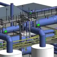
United state's beautiful refinery bird view 👍

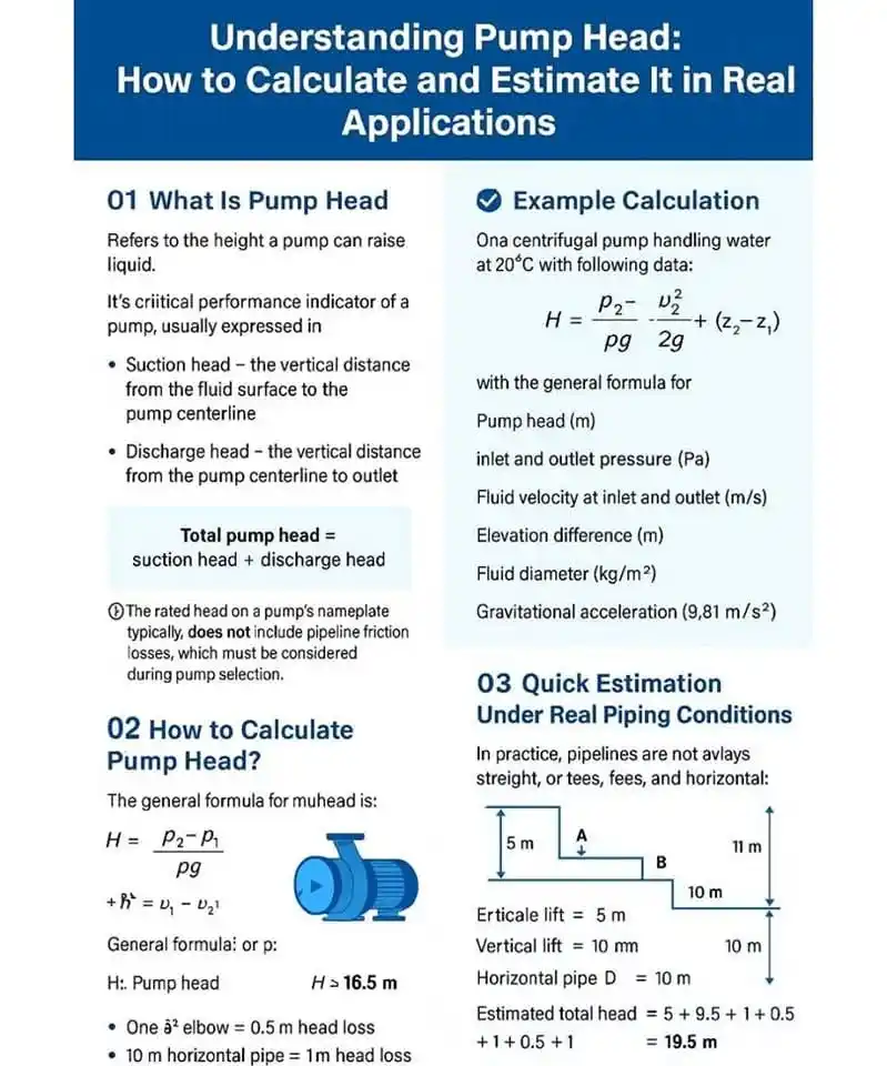
Understanding Pump Head - How to Calculate and Estimate it in Real World Applications‼️✅ Whether you're an engineer, technician, or plant operator - understanding pump head is essential for proper pump selection and system design. This visual guide breaks it down: What is pump head (suction + discharge) How to calculate it using Bernoulli-based formulas How to quickly estimate pump head under real piping conditions (tees, elbows, elevations, etc.) Includes practical tips like: Each 90° elbow ≈ 0.5 m head loss 10 m of horizontal pipe ≈ 1 m head loss Quick calculation with vertical & horizontal segments Real-life example included for a centrifugal pump handling water at 20°C! A must-share for mechanical/process engineers, EPC professionals, and anyone in fluid handling or pipeline systems. Save this for your next project and share it with your team! #MechanicalEngineering #Process Engineering #PumpHead #Fluid Mechanics #Engineering Tips #PipingDesign #Centrifugal Pump #LinkedInLearning #Chemical Engineering #PlantDesign #ProjectEngineering